Nancy Grace Roman Observatory Pointing Angles
Reference Frame Definitions
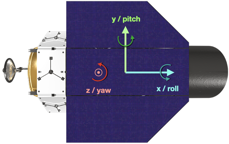
We define the Roman body-fixed (or body-centered) reference frame (\(\mathcal B\)) via the mutually orthogonal unit vectors \({\hat{\mathbf{x}}}, {\hat{\mathbf{y}}}, {\hat{\mathbf{z}}}\), with the coordinate origin at the spacecraft’s center of mass (COM; \(R\)) such that \(\mathcal B = (R, {\hat{\mathbf{x}}}, {\hat{\mathbf{y}}}, {\hat{\mathbf{z}}})\). As in the figure, below, \({\hat{\mathbf{z}}}\) is orthogonal to the surface of the solar panels, \({\hat{\mathbf{x}}}\) is parallel to the center of the barrel, and \({\hat{\mathbf{y}}} = {\hat{\mathbf{z}}} \times {\hat{\mathbf{x}}}\).
We define an ecliptic inertial reference frame \(\mathcal I = (O, {\hat{\mathbf{e}}}_1, {\hat{\mathbf{e}}}_2, {\hat{\mathbf{e}}}_3)\) where \(O\) is the solar system barycenter, \({\hat{\mathbf{e}}}_1, {\hat{\mathbf{e}}}_2\) are in the ecliptic plane, and \({\hat{\mathbf{e}}}_3\) is the direction of ecliptic north. \({\hat{\mathbf{e}}}_1\) is first unit vector of ICRS (i.e., the vernal equinox direction or the first point of Aries). The specification of coordinates may be either via the mean equinox of epoch or true equinox of date, so long as all coordinates are self-consistent.
Pointing Angle Definitions
Roman pointing commands are described as a set of 3 ordered rotations about body-fixed axes in the order: \({\hat{\mathbf{z}}}, {\hat{\mathbf{y}}}, {\hat{\mathbf{x}}}\). The angles are labeled yaw, pitch, roll, respectively and denoted by \(\psi, \theta, \phi\), respectively. The relationship between the orientation of Roman post re-pointing to its orientation pre re-pointing is therefore:
Zero-point Definition
The zero-point for Roman pointing calculations is defined with \({\hat{\mathbf{z}}}\) pointing directly at the sun (denoted by \(\odot\)), such that \({\hat{\mathbf{z}}} \parallel \mathbf r_{\odot/R}\), where $ \mathbf `r_{:nbsphinx-math:odot`/R}$ is the vector from Roman’s COM to the sun. In order to establish the relationship between the zero-point spacecraft orientation and our inertial frame, we initially orient Roman such that \(\mathcal B\) is fully aligned with \(\mathcal I\):
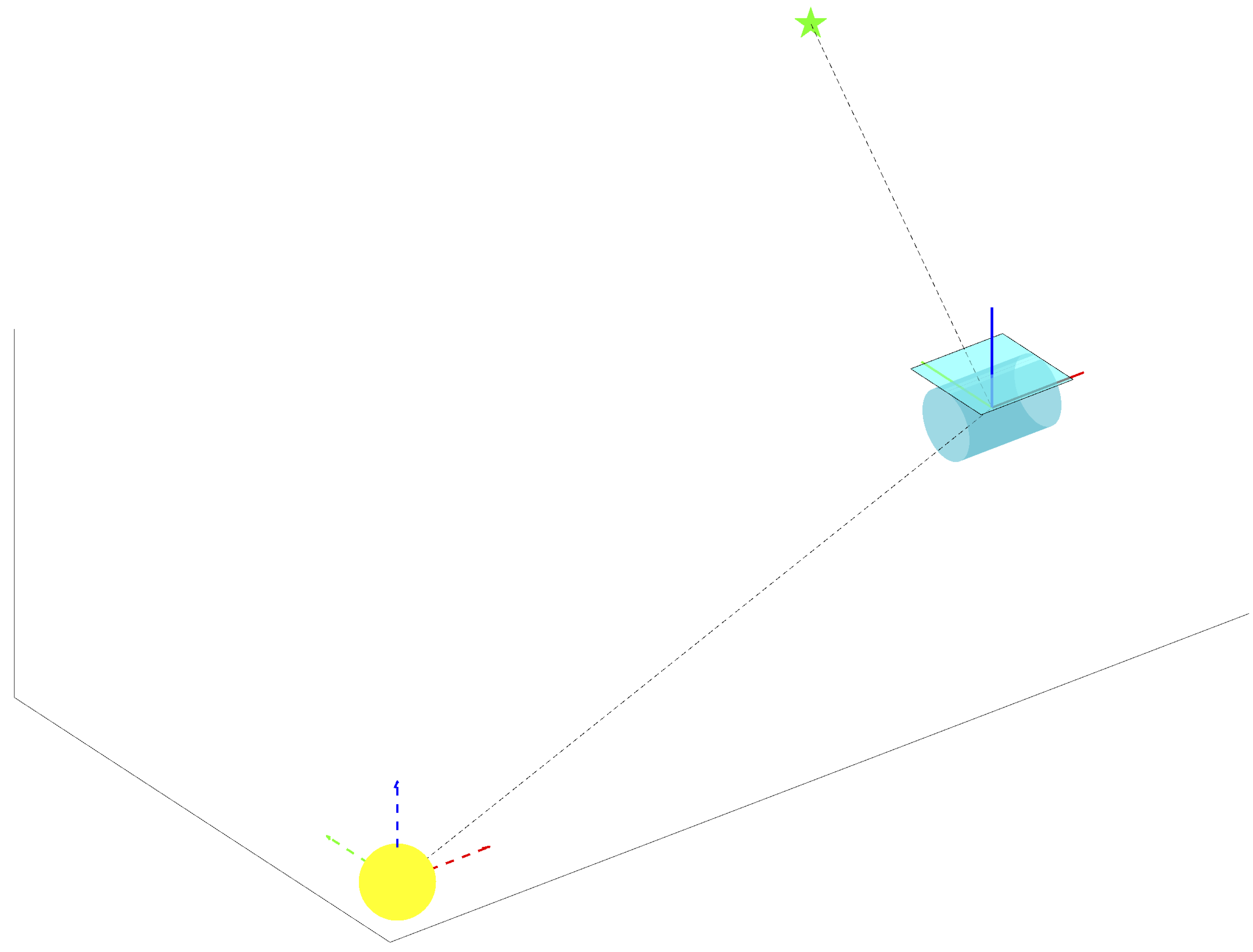
In this, and all subsequent figures, the dashed, colored lines indicate frame \(\mathcal I\) and solid, colored line indicate frame \(\mathcal B\). The ordering of unit vectors in each case is denoted by red, green, blue (such that the solid blue line is the \({\hat{\mathbf{z}}}\) direction.
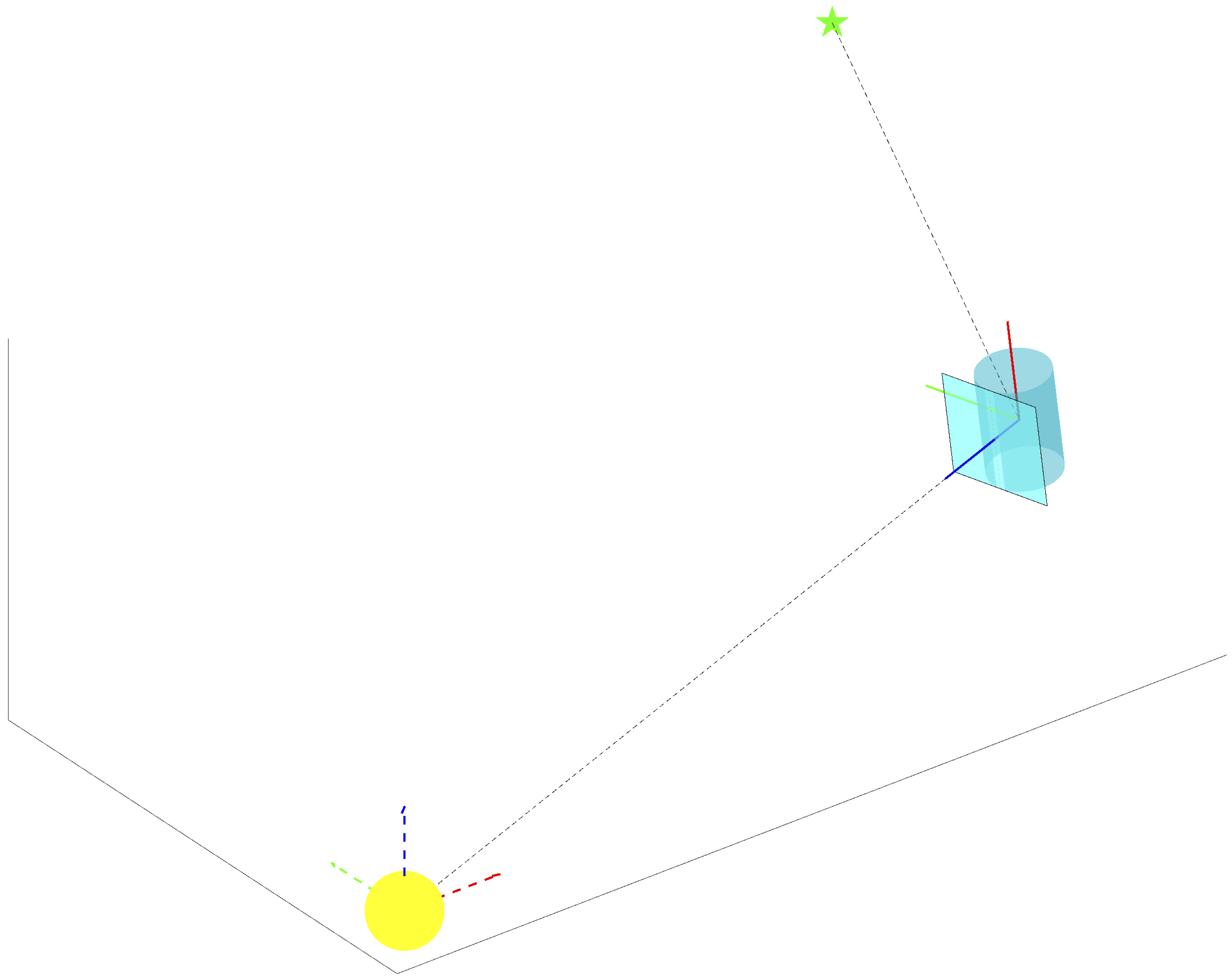
We can then compute two sequential rotations to align \({\hat{\mathbf{z}}}\) with \(\mathbf r_{\odot/R}\). The first will be about \({\hat{\mathbf{y}}}\) by the angle between \({\hat{\mathbf{e}}}_3\) and the projection of \(\mathbf r_{\odot/R}\) onto the \({\hat{\mathbf{e}}}_1-{\hat{\mathbf{e}}}_3\) plane, which we’ll denote as \(\alpha_1\). The second rotation will be about \({\hat{\mathbf{x}}}\) by the angle between \(\mathbf r_{\odot/R}\) and \(\mathbf{\hat{z}}\), which we’ll call \(\alpha_2\). Therefore, the DCM relating \(\mathcal I\) to the zero-point orientation for a given observatory location is given by:
The final zero-point orientation thus leaves \(\mathbf{\hat{z}}\) aligned with the spacecraft-sun direction:
Yaw Zero-point
It is important to note that the zero-point orientation of \({\hat{\mathbf{x}}}\) and \({\hat{\mathbf{y}}}\) is entirely arbitrary and unimportant for the calculation of pitch and roll angles. Any change to the initial orientation of these directions would be accomplished via rotation about \({\hat{\mathbf{z}}}\) (yaw). As yaw is also the first element of the pointing angle set (such that yaw changes are executed first in aligning with a new target), this would represent two sequential yaw changes, which is equivalent to a single yaw maneuver. That is, \(C_3(\theta_1)C_3(\theta_2) \equiv C_3(\theta_1+\theta_2)\). The values of the pitch and roll angles are entirely decoupled from this, so changing the \({\hat{\mathbf{x}}},{\hat{\mathbf{y}}}\) zero-point orientation only impacts the computed yaw maneuver, which is essentially unrestricted for Roman.
Target Pointing
Given a target star’s barycentric ecliptic longitude and latitude at the epoch of observation \((\lambda, \beta)\), along with the stellar distance \(d\), we can write:
We subtract the observatory’s barycentric position from this vector to get the observatory-star look vector:
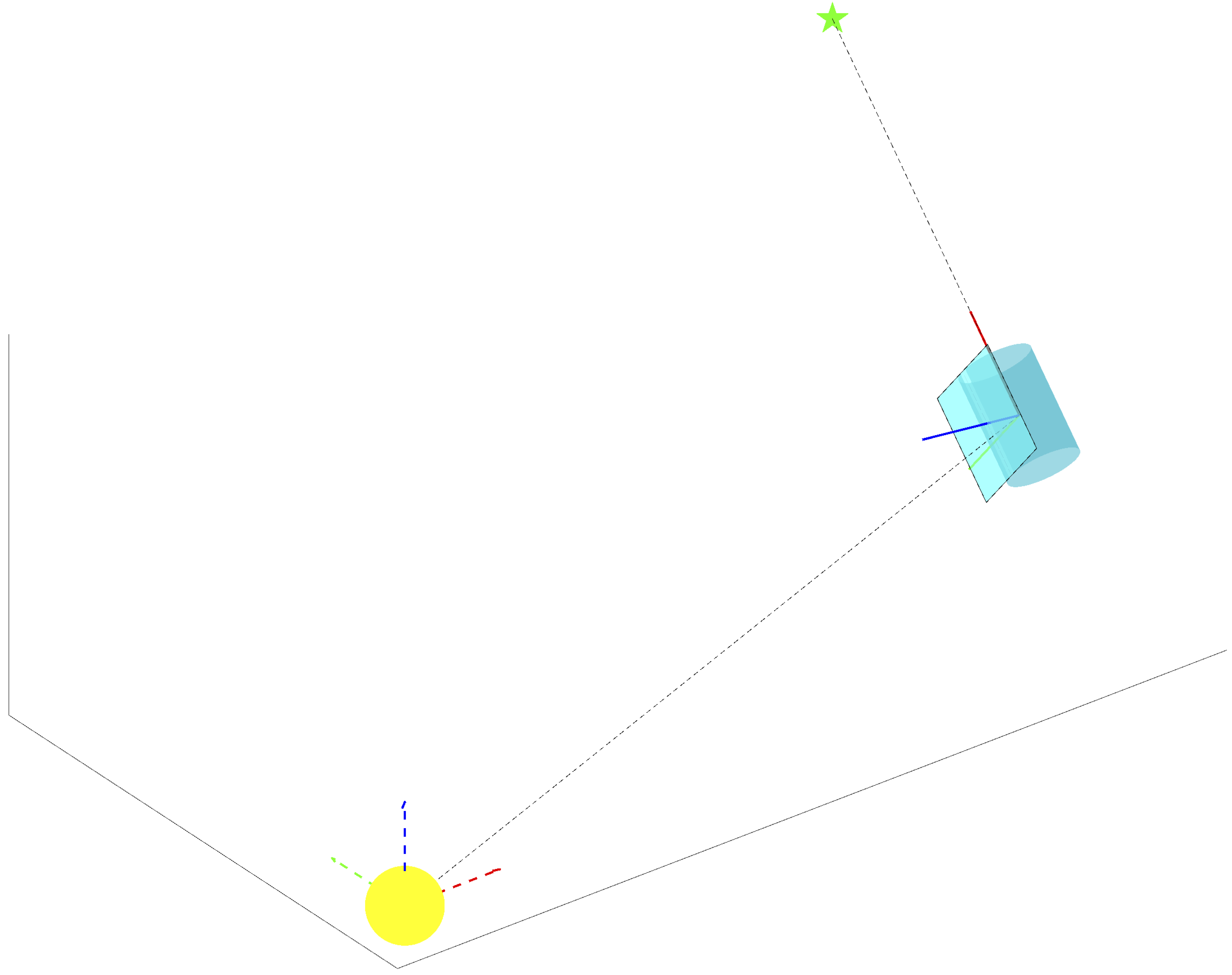
To align the boresight (\(\hat{\mathbf{x}}\)) with the look vector, we first rotate about the \(\mathbf{\hat{z}}\) axis by the yaw angle (\(\psi\)), which is equal to the angle between \(\hat{\mathbf{x}}\) and the projection of \(\mathbf r_{\star/G}\) onto the \(\hat{\mathbf{x}} - \hat{\mathbf{y}}\) plane. We then rotate about \(\hat{\mathbf{y}}\) by the pitch angle (\(\theta\)), which is equal to the angle between \(\hat{\mathbf{x}}\) and \(\hat{\mathbf{r}}_{\star/G}\). This leaves \(\hat{\mathbf{x}}\) parallel to the spacecraft-target vector:
[ ]: